Introduction
The radar receiver (Rx) is fully controlled via the instrument's software interface. Once launched the application has several functionality clusters grouped into tabs:
- Hardware settings
- User inputs
- DataView 1D
- DataView 2D
- Power Management
Tip
At start up, the Power Management screen is always shown first to remind the operator it is important to check these settings.
Power Management Tab
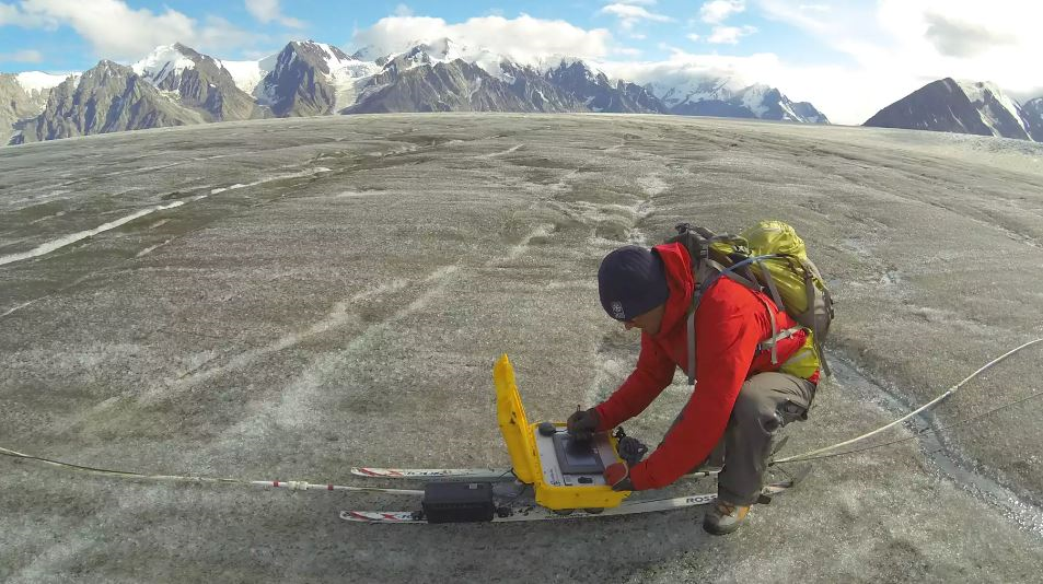
Battery check is one of the tasks the radar system's operator must do regularly during a survey. The goal is to minimize the chances of the system losing power abruptly if the battery runs out, and if so preventing an orderly shutdown of the software system. In this case, there would be a risk of data corruption, potentially compromising hours of surveying. Even though this risk is small, it is not negligible and power status must be well managed to avoid an unintentional power brownout.
- Knowledge of the battery type/chemistry will determine what Shutdown Level (V) to prescribe. This voltage level will be used as the threshold at which the system will automatically turn off.
- The Shutdown Level (V) is set such that the system has enouhg time to shutdown gracefully (about 1 min).
- The Check Period is the number of minutes between each check.
- The GUI_VBattFactor is a coefficient that allows to tune the software voltage reading to the analog indicator...
- ...the analog indicator is on the main panel of the EPU and is easy to monitor, with readouts operating as soon as a battery is connected to the system.
Tip
- For a nominal 14.8V LiIon battery with an internal monitoring IC, the level should be set above the battery's internal cut-off at around 12.2 V (see battery section for more details)
- For a 12V nominal GelCel battery, there is no cut off, and the level can be set at around 11 V.
Warning
If the radar system is being powered from wall power, for instance in a lab setting for training purpose, the AC/DC cable/converter will provide ~ 12V, which is lower than what a cut-off level might have been set at. Be sure to reset the cut-off accordingly before doing a voltage check, otherwise the system will interpret the new battery voltage level as being too low, and will shut down.
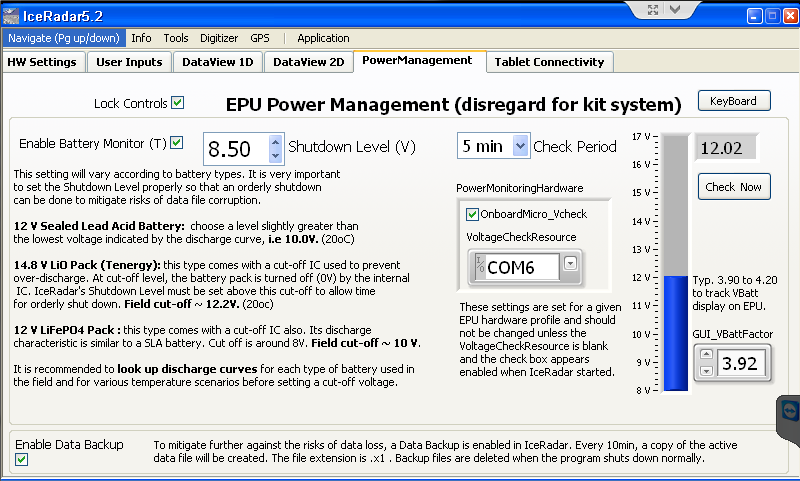
- The Enable Data Backup is another built-in protection against potential data loss in the case of power brownout. A double backup scheme is implemented by saving a first copy of the current data file while the system is acquiring data. Then when it is time for an update, a new backup is created before deleting the original backup. This way there is always one backup available and not being open by any application, so free of data corruption risk.
Caution
There are a few caveats to be aware with this procedure:
- Disk usage can become large as there is at one point 2x copies of the original data on disk plus the original file. This was more of an issue with older systems that had a more limited disk space.
- When files get large, i.e. several hundred of MB, the backup operation can take a few seconds, during which the acquisition tasks are on hold leading to a brief time step increase between acquired locations.
- This pause is usually easily recognizable on the live GPS plot (DataView 1D tab) and appears as a jump in the otherwise smooth GPS track
- For these reasons, it is suggested to monitor the data file size and start a new data file once the size reaches ~ 150MB- 200MB.
Hardware Setup Tab
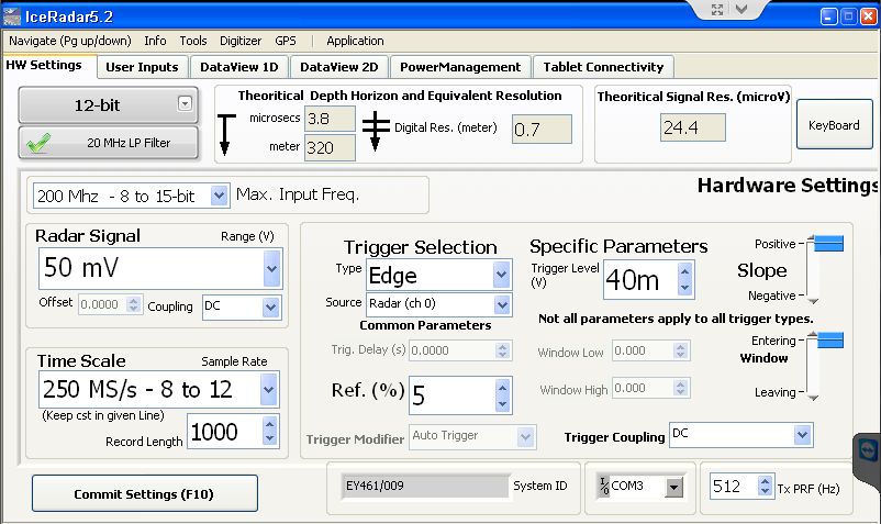
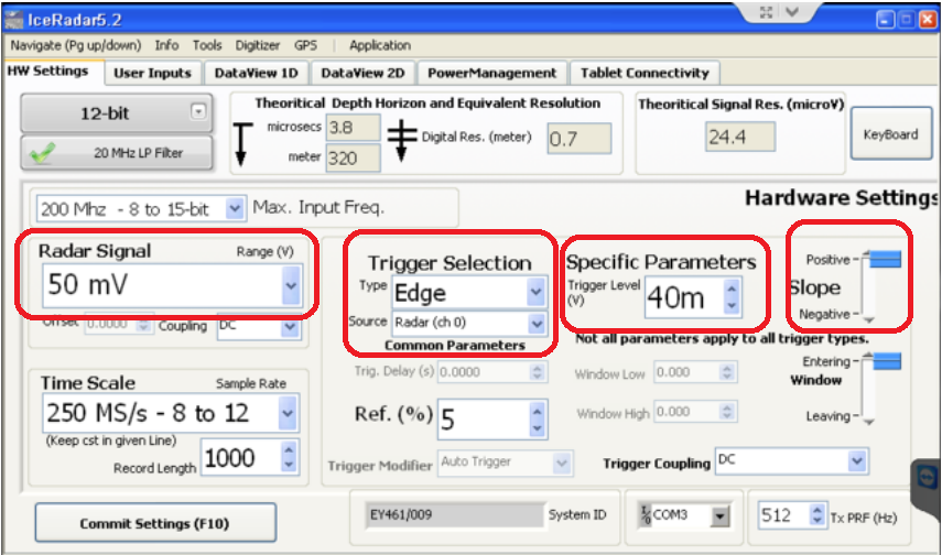
The Hardware Settings tab contains the most complex group of parameters. However, once familiar with its settings, there is only few adjustments to make. In versions >= 5.0, Theoritical Depth Horizon and Equivalent Resolution group and the Theoritical Signal Resolution (microV) group were added.
Time Related Settings (relating to ice-depth)
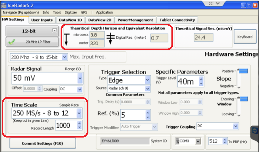
- Ice depth horizon and Sample Rate, Record Length pair: Sample Rate in megasamples/sec and Record Lengths in samples define the ice-depth horizon in meters at which the EPU will collect data. This can also be expressed as the duration (microseconds) that the EPU will acquire data once a trigger is detected. This duration relates to the two-way travel time (TWTT) of the radar pulse.
- During this time, the radar pulse travels from the transmitter's antennas, into the ice, reflects off a target (the bed or other significant reflecting horizon). Part of this reflected signal is then captured by the receiver antenna and into the EPU providing a time varying voltage. Time and distance are linked by the electromagnetic (EM) wave speed in ice, typically given as 0.168m/ns, roughly half the speed of light in a vacuum or air.
-
This is expressed in the Theoritical Depth Horizon and Equivalent Resolution indicators group:
- For instance: a sampling rate of 250 MS/s and record length of 1000 samples is equivalent to ~ 4 microsec of TWTT.
- At the speed of EM wave in the ice of 0.168 m/ns , or 168 m/microsec, this corresponds to ~ 168*4 = 672 m two-way travel distance.
- Now considering the EM pulse covers twice the distance equivalent to the ice thickness (to and from the reflector), we obtain an actual depth of 672/2 = 336 m.
- If we consider the separation between transmitter and receiver, and assume the direct wave (air wave) travels at the speed of light between them, the actual TWTT becomes ~ 3.8 microsec, and horizon depth ~ 320m
-
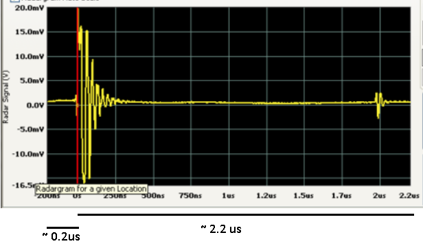
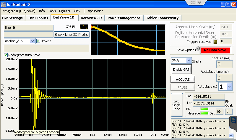
The Ref(%) setting indicates at which percentage of the entire width of the time window, the trigger event is positioned. In the example shown below, the direct wave starts at about 0.2 microsec from the start of the horizontal scale, while the full scale is 2.2+0.2 = 2.4 microsec, so the Ref setting was at 0.2/2.4~ 8% .
- Typically this setting would be set at 5 or 10% and allows for a full view of the direct wave
Note
The larger Ref(%), the more centered the direct wave position on the graph is, showing more pre-triggered data, and less post-triggered data (from deeper into the ice).
Caution
Sampling rate:
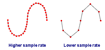
- Higher sampling rate: better signal reconstruction
- Higher sampling rate: larger data file for a given depth horizon
- Sampling rate needs to be at least 2x the highest frequency content of the radar signal (Nyquist), in practise, 5x is good, 10x is best.
Time Related Settings - Newer Models
In software version > 5.0, the instrument's digitizing board offers faster sampling rate(s) and better resolution (up to 16 bit). The allowed combination of Sampling Rate and Resolution (ie, the number of bits) is mostly taken care of by the software. It is nonetheless important to know what they are.
- IceRadar versions up to 4.x
| Bandwidth | Max Sampling Rate | Resolution | Smaller inpur Range |
|---|---|---|---|
| 100 MHz | 250 MS/s | 12 bit | +/- 50 mV |
- IceRadar versions 5.x
| Bandwidth | Max Sampling Rate | Resolution | Smaller input Range |
|---|---|---|---|
| 200 MHz | 1 GS/s | 8 bit | +/- 10 mV |
| 200 MHz | 500 MS/s | 12 bit | +/- 20 mV |
| 200 MHz | 250 MS/s | 12 bit | +/- 20 mV |
| 200 MHz | 125 MS/s | 15 bit | +/- 50 mV |
| 200 MHz | 125 MS/s | 12 bit | +/- 20 mV |
| 200 MHz | 62.5 MS/s | 16 bit | +/- 50 mV |
Note
When the 20 MHz filter is enabled, the bandwidth is limited to 20 MHz, improving the signal-to-noise ratio (SNR) when the signal's frequencies of interest are below the filter rating. This only applies to IceRadar models > 5.x
Caution
When the operator increases the Sampling rate, the Resolution dropdown adjusts automatically its maximum allowed value. However, when the Sampling rate is decreased, the system does not assume the resolution should follow suit.
Signal Amplitude Settings (signal strength, and amplitude resolution)
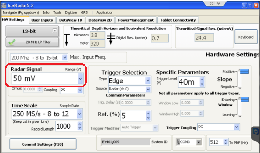
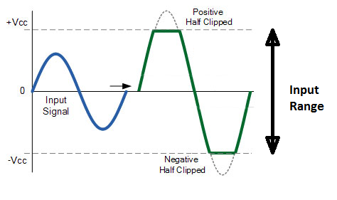
This setting defines the bipolar amplitude range (i.e +/- 50mV) the input electronics is set at. All the digitization capabilities of the instrument will be spread over the range span (i.e 100mV span in this case). In this illustration, part of the radar signal greater than 50mV will be clipped. Increasing the input range will allow a wider span of the input signal to be digitized, at the cost of a diminished (less accurate) vertical resolution.
Note
Typically the direct wave is clipped when the instrument is set to the best possible resolution in order to detect weak signals from deep reflectors of interest.
- 2^n levels, with n = number of bits
- Relates to voltage amplitude of radar signal

Note
- 3-bit ADC --> 2^3 = 8 levels
- 12-bit ADC --> 2^12 = 4096 levels
- 16-bit ADC--> 2^16 = 65536 levels
- with derived Voltage Resolution: Vref/2^n
- The more bits, the smaller (better) the resolution, the smaller voltage one can resolve
More readings:
-
Acquiring an Analog Signal : including topics such as bandwidth, amplitude error, rise time, sample rate, the Nyquist Sampling Theorem, aliasing, and resolution.
Trigger Settings
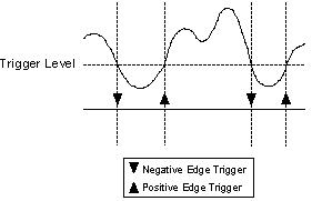
A trigger is an external stimulus that initiates one or more instrument functions. Generally speaking, trigger stimuli include digital edges, software functions, and analog levels. The proper trigger can be derived from attributes of the signal to be acquired, such as the magnitute and slope of the signal. In the current version of the software options are either Edge or Immediate (no trigger). An edge trigger occurs when a signal crosses a user-selectable threshold defined in mV
More refinement can be obtained if you can specify the slope as either positive (on the rising edge) or negative (on the falling edge). The following figure shows edge triggering with different slope selections
Tip
Typical settings are an input range of 50mV with a positive (rising) slope trigger set at a ~ 45mV level. The signal source is Radar (Ch 0).
Warning
The Trigger Slope is only positive for a given antenna layout as described in the deployment section. If the antennas layout is flipped, the first arrival of the direct wave will be on the negative pulse, requiring the trigger settings to be adjusted accordingly.
User Inputs Tab
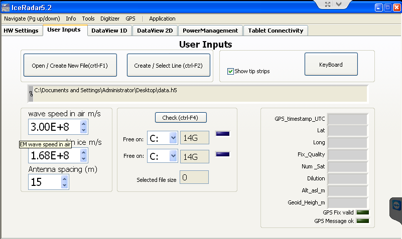
Under this tab the user can input the Wave Parameters, notably the wave velocity in air, the wave velocity in ice, and the antenna spacing settings.
As a guideline here is the distance used between transmitter and receiver when used in-line (one behind the other)
| Center Freq. | Arm Length | Separation |
|---|---|---|
| 5 MHz | 8.4 m | ~ 30-35 m |
| 10 Mhz | 4.2 m | ~ 15 m |
| 30 MHz | 1.4 m | ~ 5 m |
| 40 MHz | 1.1 m | ~ 4 m |
| 50 MHz | 0.8 m | ~ 3.5 m |
...more details about this are found in the Rx-Tx separtion section.
This tab is also used to set the file where data will be stored. Next, the user can select two volumes or hard drives present on the system to check their size comparatively to the data file. It is recommended to regularly check the solid state drive capacity. Finally, this window also provides the user with the full GPS reading parsed from the $GGA NMEA message.
DataView 1D Tab
When not acquiring, the Acquire box is grey, and the data save control is set to No Data Saved in red.
Complete "Acquire" settings must show the following:
- Auto-Save : Green
- Enabled GPS: Green
- also verifying the GPS gets a fix (green LED),
- and the GPS Message is ok (green LED).
- Acquire : Green
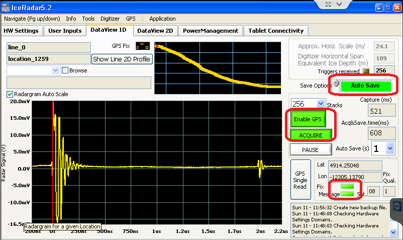
The Auto-Save (s) setting indicate the rate at which a new location data save will be run.
DataView 2D Tab
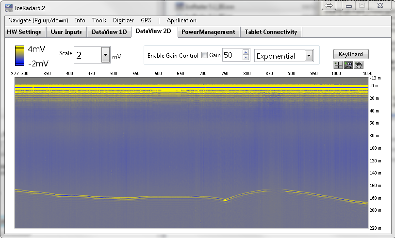
Note
The Gain control (GC) and filter settings, are only for display and do not alter the acquired data
Data Saving
IceRadar uses a hierarchical data format to store information (HDF5).
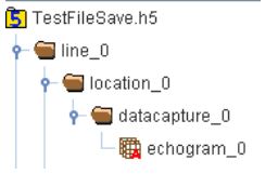
- Data are first grouped into a top level object, called a Line that represents a logical grouping of measurement locations on the terrain.
- For each physical location, a subgroup object called a Location is defined.
- In turns, the Location object contains datasets grouped into a datacapture object, linking together the radar data, the GPS data, and the computed depth data.
- All these objects can have Attributes (Meta data) associated to them.
The resulting dataset for Line_0 at Location_0 is :
../location_0/datacapture_0/echogram_0
All the data is consolidated into the hierarchical file system, and can be accessed by the analysis routines. IceRadarAnalyzer is such a routine, however many development environments and languages like Matlab, Python, etc... have HDF5 libraries available.
Backing up the System
To back up the IceRadar system and OS the following procedure is suggested:
- One option is to create a full image of the SSD that can then be restored later if needed
- To back-up IceRadar executables:
- Navigate to the location of the exe file
- backup to an external drive the entire folder containing the application
- to restore: copy the backed up copy into any location and create a shortcut to the exe application. These applications require NI LabVIEW Runtime engine 2011 and NI-VISA 5.4.0 that can be downloaded from www.ni.com.
Note that the IceRadar software is provided as a licensed system for 1x radar system and as such cannot be copied to other computers.