The same principles apply whether the system is used for self-propelled surveys conducted on skis or foot, or with a snow machine.
In general terms, a self-propelled setup needs to be lighter and will use smaller batteries than a snow machine setup. A crew of three is ideal for a ski survey, but two can be sufficient if travelling conditions are favorable and the crew is experienced in using the system and navigating with long antennas. Snow machine surveys are routinely carried out by one experience crew. As a rule of thumb, terrain and glacier surface conditions will always directly impact the complexity of carrying out a radar survey.
General principles
The basic principle to operate the equipment successfuly is to make sure that:
- all the strain-relief components are properly in place. Antennas, by design are light and made of wire with resistors inserted along the way (resistivily-loaded dipole), and even though they are protected inside a hose, they require care.
- strain-reliefs are regularly checked during a survey
- a pull rope is always used, so that no pulling is applied to the protecting hose.
Tip
We found that the most effective and field-reproducible approach to secure strain reliefs was to use prussik ropes as shown in the panels below. This approach minimizes specific hardware that would be harder to replace in the field. Ropes and cords should be readily available with the rest of the safety equipment used in the field.
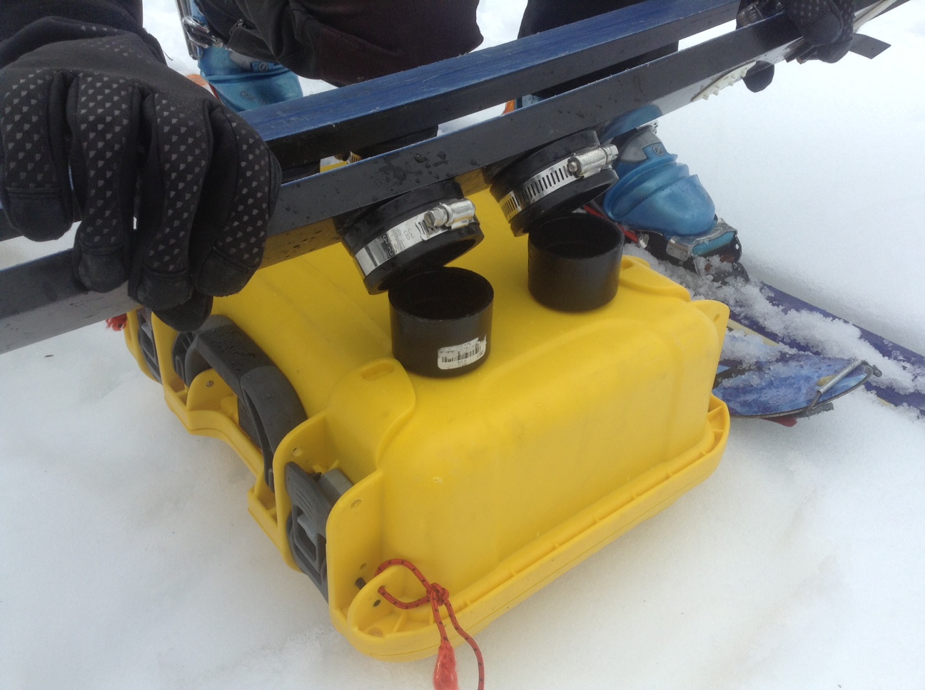
Mounting EPU on glide system
Make sure EPU's binding cups are fully inserted into rubber cups for a secure attachment.
Ski or foot surveys
For foot or ski surveys the principles remains: preventing any mechanical stress damaging the antennas, and the feed-point attachments to transmitter and receiver. For foot or ski survey, it is necessary to achieve effective system rigging and protection with as low a weight as possible and as simply as possible so it remains easily maintainable.
Strain reliefs
Warning
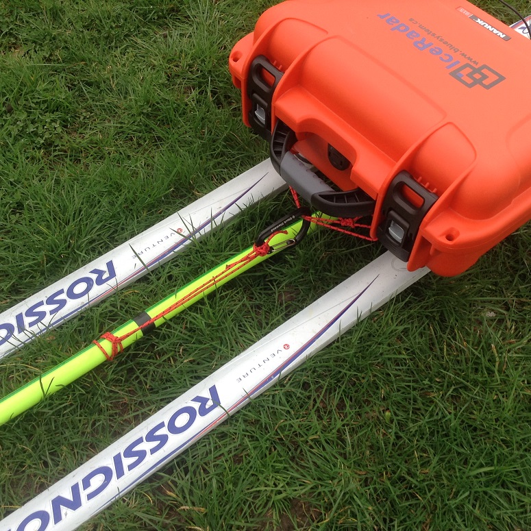
Strain relief on the Rx (front and back) and Tx (front) are critical. They prevent unwanted tension on the antenna protection.
All the tension must be maintained on the Rx and Tx enclosures. To achieve this a set of cords on each enclosure and a carabiners tied to a prussik cord for easy adjustment are placed on each location where the protective tubing is to be linked to the enclosures.
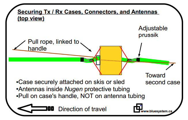
A first strain relief must link to the front of the Rx and Tx enclosure. The prussik system allows to adjust the tension easily with no tools.
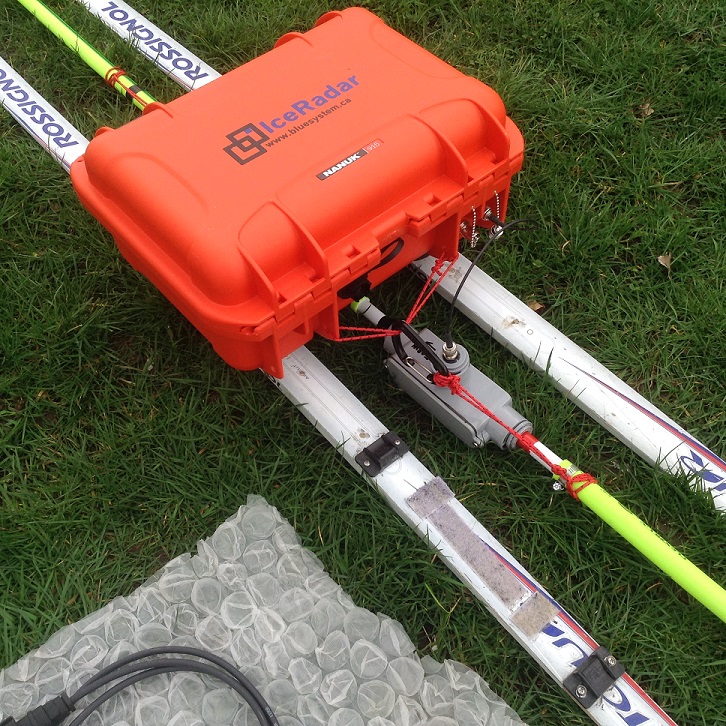
Similarly, in the back of the enclosure (only for Rx), an identical strain relief setup as in the above image is mounted: This is critical as it prevents tension on the BNC connector linking the antenna feedpoint to the enclosure RF input.
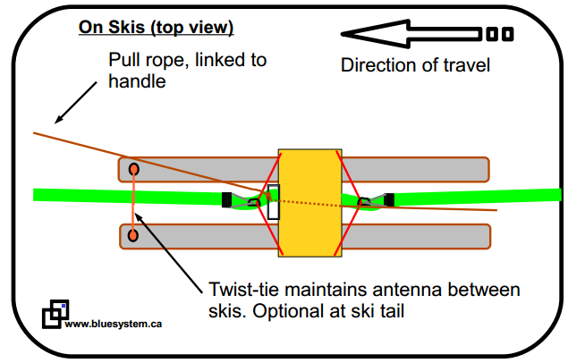
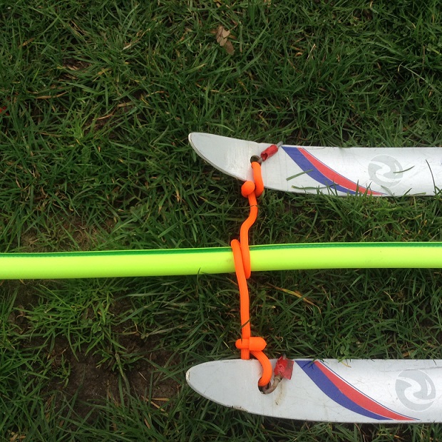
Finally, to better control the position of the antenna protection between the skis, the following accessories is added, linking the ski tips with the antenna.
Pulling the system
Snow condition dictates how effective it is to pull the system along the ice surface. Typically, conditions with low ski-penetration are best to ease trail-breaking both from the skier's perspective and sled's potential plowing due to deep snow. As always, it is critical to minimize tension on the antennas.
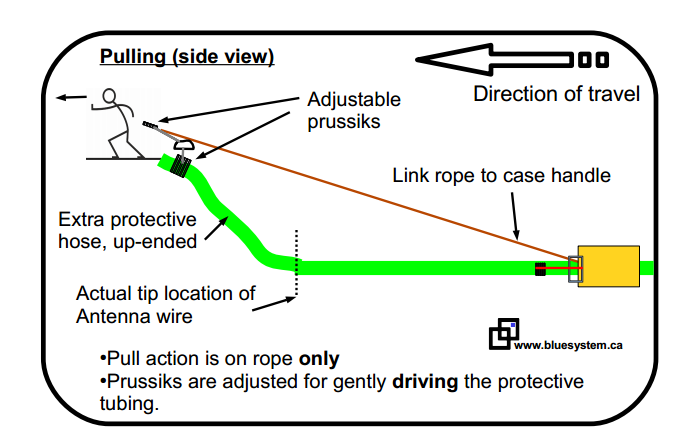
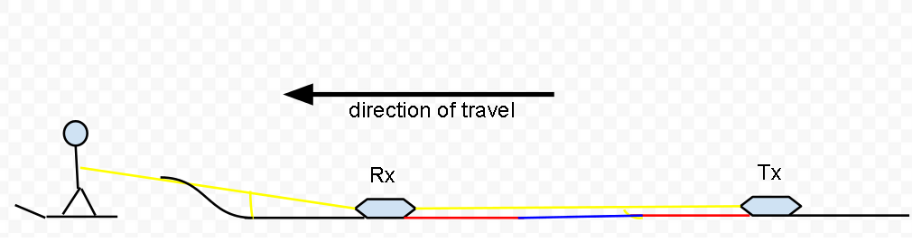
For this reason a pulling rope running from the Main Pull (lead) to the first, and second sled is required. No Pull is applied on the protective hose, while maintaining its leading edge above the snow surface. This is done by installing a prussik rope from the end of the protective tubing to the pulling rope. This will keep just enough tension on the tubing to keep its front end off the ice surface, insuring no travel impediment. Note that the antenna's actual front end, inside the protective tubing, is located 2 to 3 m from the protection's extremity. It insures the antenna remains in contact with the ice surface despite the protection hose extremity being off the ground.
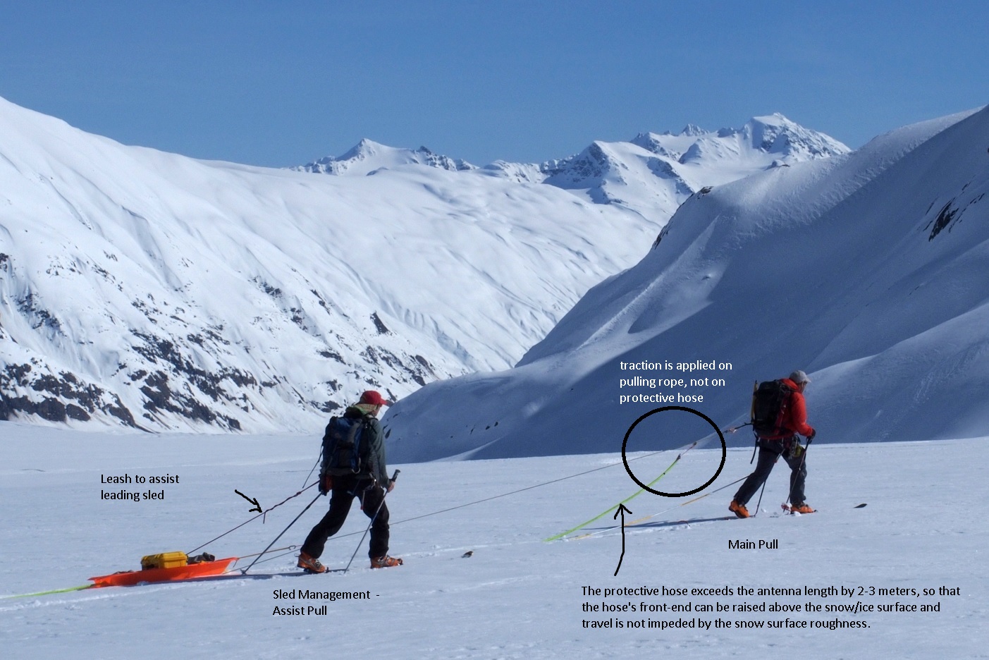
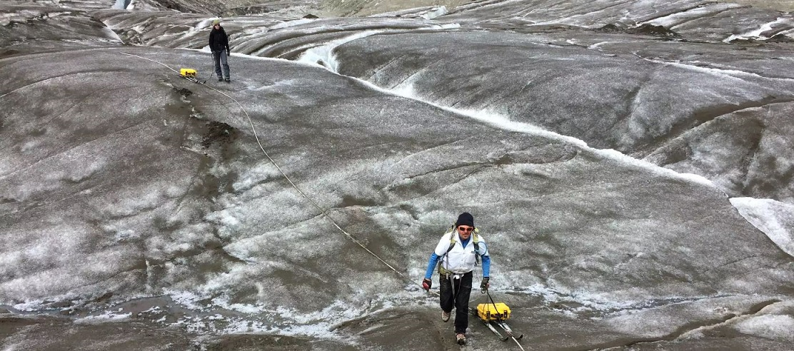
Typically the person in the lead is in charge of the glacier travel, and terrain assessment. She/he should maintain a regular pace, and be focused on travel safety.
Behind the lead person (not shown on the image), the Rx sled (either on skis, or a pulk) requires one person to insure smooth travel around potential obstacles. A simple leash is usually enough. The person at this position also manages the system operation via the radar software. It should be the team member with the most radar operation experience located by the Rx unit.
Finally, a third operator can be located by the Tx sled at the back, with a leash as well. Check on Tx operation is sometimes required. This position is usually the easiest of the three except while going downhill where more control have to be applied by slowing down the whole system to maintain a constant distance between the sleds.
Note that a double-tape mark indicates the position of the antenna edge. So for the leading edge being lifted above ground, keeping track of this mark insures the actual active antenna full length stays in contact with the ice surface. Alternatively, the antenna core can be felt through the hose with bare hands by applying gentle pressure on the hose wall.

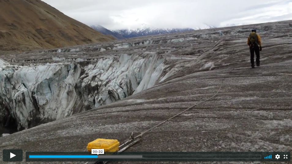
Videos: Pulling the system
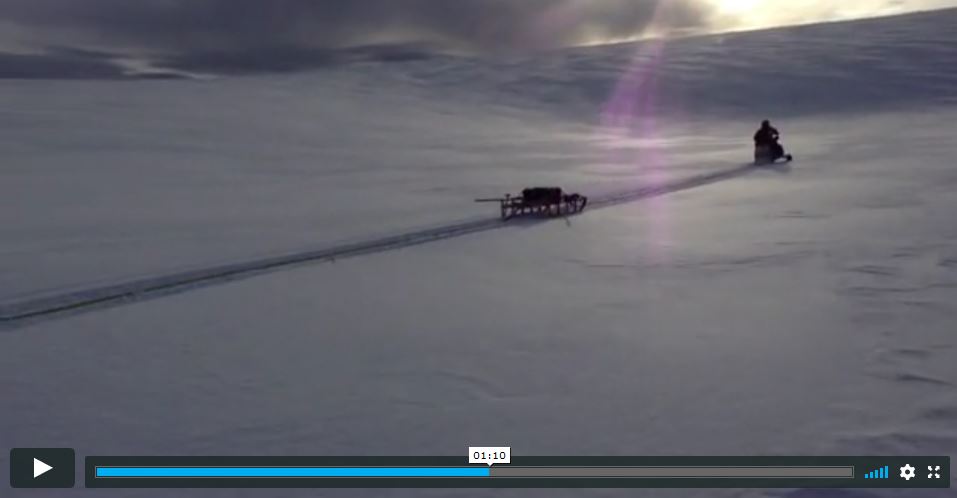
The videos below give a good overview of a self-propelled setup.
Good travelling conditions
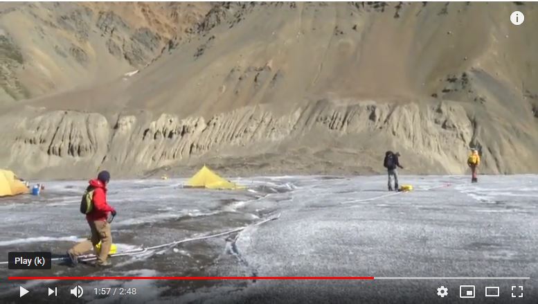
Difficult travelling conditions
The video segment of interest starts at 2:44 min and gives another perspective from the lead person (in not so favorable surveying conditions in very slushy snow).
Antenna setup
Arms position
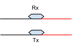
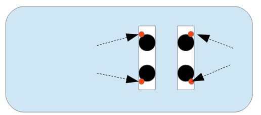
The protective tubing length for each antenna arm is set so that field deployment is done as follow from left to right on the diagram:
- Leading arm (black, negative Rx arm), with extra length off the ice surface
- Rx sled
- Rx positive arm (red)
- link section
- Tx positive arm (red)
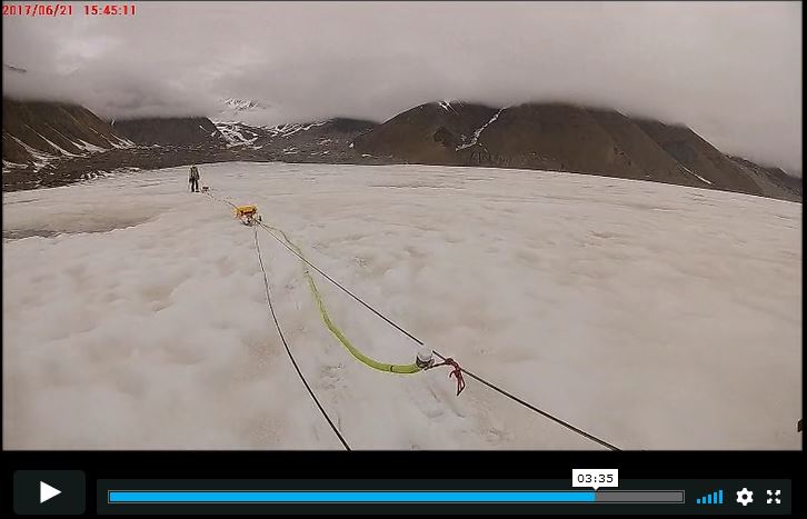
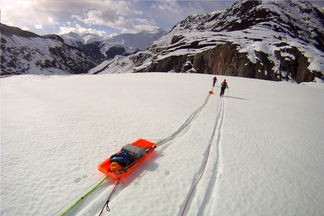
In the image below, from the perspective of the third team member at the back near Tx, one can see the system is well deployed with stable sleds, antennas straight and constant spacing between sleds. The link section is visible between the sleds and blends with the two Rx and Tx antenna arms between the sleds.
Rx-Tx separation on glacier ice
Rx-Tx separation scales with antenna's center frequency/length. Too close and ringing is more likely, too far apart, and the signal strength of the direct wave decreases. This has no impact on the reflected signal strength from englacial reflectors. Rx and Tx should be arrange in-line.
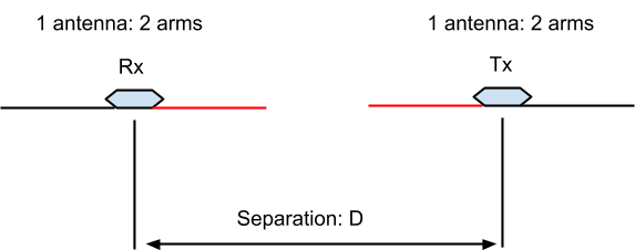
| Center Freq. | Arm Length | Separation |
|---|---|---|
| 5 MHz | 8.4 m | ~ 30-35 m |
| 10 Mhz | 4.2 m | ~ 15 m |
| 30 MHz | 1.4 m | ~ 5 m |
| 40 MHz | 1.1 m | ~ 4 m |
| 50 MHz | 0.8 m | ~ 3.5 m |
Tip
If the system is tested off the ice, such as an urban or semi-urban environment, a large area like a sport field is recommended. In this case, Rx and Tx should be arranged in a parallel configuration (as opposed to in-line).
Also, the Rx-Tx separation should be shorter compared to the above figures in response to the direct wave's changing characteristic in a different propagation material.
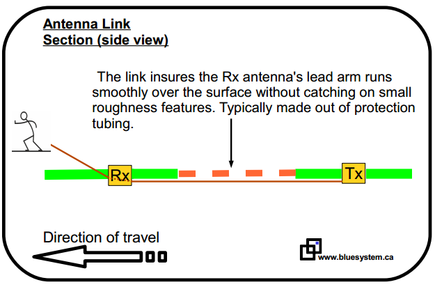
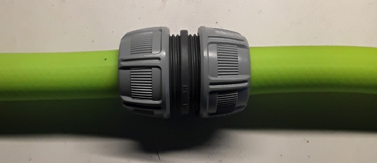
Antenna link accessory
Tx and Rx antenna arms are connected with a link section that is made of the same hose protection as the antenna sections and are linked with a junction accessory. The accessory may have different sizes depending on availability at the time of the system building. Under specific ice surface conditions (bare ice), it has the potential to get caught into centimeter-size crevasses or surface cracks with the potential for pull-outs of each hose sections.
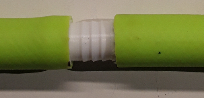
On latest systems, a double-barb insert is provided as an optional link accessory.
Snow machine surveys
There are two main considerations when using the radar system with a snow machine.
- An increased level of stress on the hardware, more specifically on the antennas, and at the antenna's feed-points into the receiver and from the transmitter, due to higher speed and torque of the snow machine compared to self-propelled.
- A higher travelling speed has to be compared to acquisition time required to obtain the required nbr of stacks. Stacking duration must be related to the traveling speed so that the distance it takes to complete the stacking operation is estimated. This consideration is usually not as important for slower moving foot surveys (~ 1m/s). More details are provided on a separate section on stacking.
As an illustration, the picture below shows the sled system built by the Institute of Earth Science in Reykjavik. All the mechanical considerations discussed above are addressed on this sled, in particular the strain-relief between sled and antenna protection.
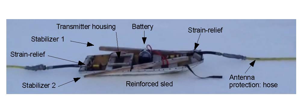 Also not shown on the picture, the tail-end of the trailing antenna is rigged with a "brake system", dragging behind the antenna and insuring it stretched out while in operation.
The video below gives a good overview of the complete setup including good views of the receiving sled.
Light snowsled as glide system
Aside from using skis, light snowsleds offer a good solution for a glide system. As described earlier in this document, the most important step is to insure strain-reliefs are well secured so that no pull takes place on the antennas.
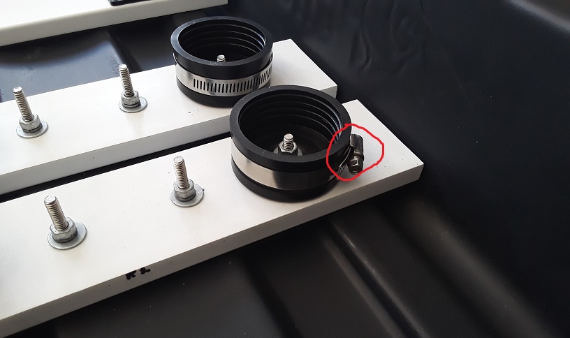
Note
Insure the tightning screw on each binding cup's o-ring remains positioned so that they can easily be reached once the radar enclosure is mounted and secured inside the binding cups.
Tip
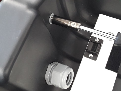
Use a 5/16 socket screw driver instead of a standard screw driver to tighten the binding cup, as once the radar enclosure is inserted, access to the o-rings is more difficult.
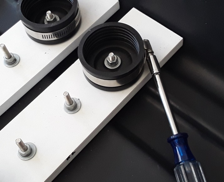
Similarly for all the other bolts, use a 7/16 socket. All bolts should be firmly secured, but not to the point of crushing the sled structure.
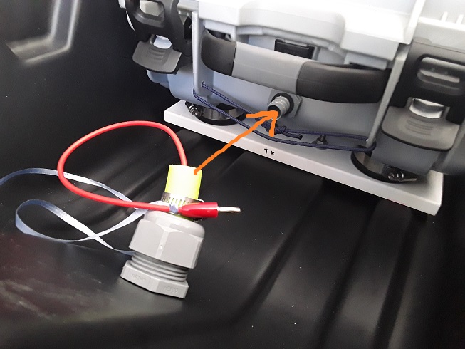
For the Tx sled, antennas can easily be inserted from the outside --> in minimizing the amount of hose having to be passed through the strain relief connector.
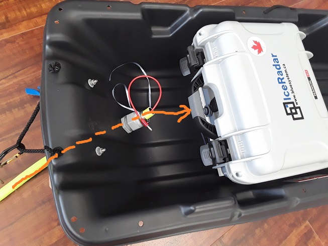
For the Rx sled, antennas are inserted from the inside --> out, since they are secured on the radar enclosure. Once the antennas are filled through the strain-relief connector.
Tip
The steps for mounting the Rx enclosure into the sled are as follows:
- insure the o-ring screws are facing out at about 45 degrees in
- install the radar enclosure securely, deep-seated in the binding cups
- tighten the o-rings
- run the antenna arms without the link section through the strain relief connector from the inside --> out
- secure the link section.