Introduction
The X-IceRadar software supports a dual-input scheme where data are acquired simulatenously on 2 channels. The radar signal is fed into two internal inputs allowing for the selection of a specific input range for each input. Useful for large direct wave signals, one channel's input range can be set so that the entire direct wave's amplitude is captured (low-res) while the other channel's input range is set as usual to maximize the signal resolution (hi-res with clipping).
This feature can be useful for:
- checking the full range signal and status of the transmitter+antennas combo
- using the full range signal as a proxy of the power entering the ice.
- move the trigger level higher to prevent potential false triggers at lower levels that may be caused by ringing or other radio signals.
Note
The input ranges and trigger level used in the following sections are used as examples. The actual settings may differ according to the direct wave's observed amplitude and reflectors' amplitudes.
- Single Channel Acquisition Mode
When the selection button remains on Single Channel Acq. Mode, the radar signal is routed into a single hardware channel.
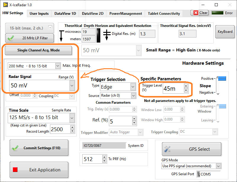 Here, the Small Range setting is greyed out, and the best possible resolution is obtained on a single channel. The 45mV trigger level in this example applies to the only available input channel and the system will acquire data with the following settings:
| Channel | Resolution | Input Range | Comments |
|---|---|---|---|
| Ch 0 | 15-bit | 50mV | hi-res channel, direct wave cut is cut-off, small signals well resolved, 45mV trigger applies to this channel |
- Dual Channel Acquisition Mode
When the selection button remains on X-Mode: Dual Channel Acq. Mode, the radar signal is routed into two hardware channels.
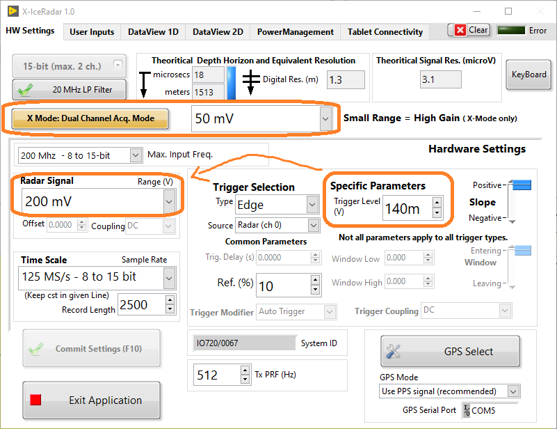
With the above settings the system will acquire data as follows:
| Channel | Resolution | Input Range | Comments |
|---|---|---|---|
| Ch 0 | 15-bit | 50mV | hi-res channel, direct wave cut is cut-off, small signals well resolved |
| Ch 1 (!) | 15-bit | 200mV | lo-res channel, direct wave not cut-off, 140mV trigger applies to this channel |
Note
(!): In Dual mode, the Small Range/Hi-res is set to the low-res channel (high range), hence the trigger level can be raised to 140mV (as in this example) well above smaller signals that could cause false triggers. Meanwhile the other channel is set to 50mV input range for hi-res acquisition.
Caution
The trigger level always applies to the input range defined inside the Hardware Settings box. For the settings to make sense, the Small Range/Hi-res must therefore show a smaller amplitude than the Radar Signal range inside the Hardware Settings box. This is the case only on Dual Channel Acq. Mode.
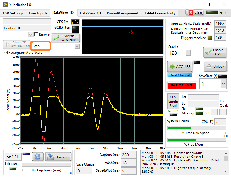
1D DataView Tab
In Dual Input Acq. Mode the dropdown selector located above the radargram is used to select which channel(s) to display.
- "Both"
As shown below, one can see in yellow the high-resolution channel that is chopped at 50mV, since in our example the hi-res input range was set at +/- 50mV. Similarly we can see in red, the low-resolution channel capturing the full signal amplitude at ~ 163mV since the range was set at +/- 200mV. Finally, the trigger level is recognized as the vertical red line, intersecting the low-res plot around 140mV
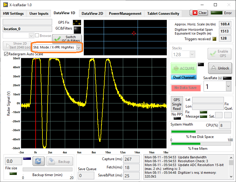
- "Std.Mode / X-IPR: HighRes"
Here, only the hi-res channel is shown, cutting off at 50mV, as per the range setting, and showing a better trace resolution than on the previous view.
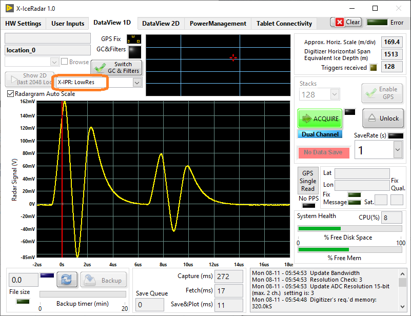
- "X-IPR: LowRes"
Finally, the low-res channel can also be shown on its own, and one can recogzine now in yellow, the red trace from the first dual plot.
Data Saving
Following the approach adopted with the standard file format, a hierarchical data format is used to store the radar data(HDF5).
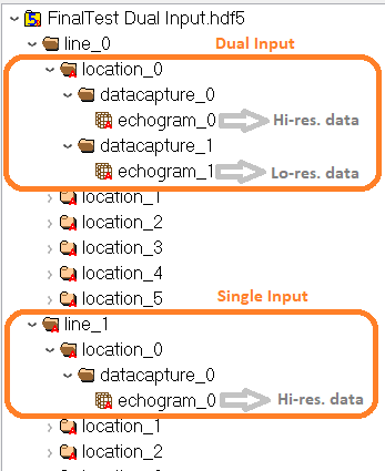
Following the Dual channel acquisition mode, the resulting data is stored as:
../location_i/datacapture_0/echogram_0for the hi-res. data../location_i/datacapture_1/echogram_1for the low-res. data (used for triggering)
... And following the Single channel acquisition mode, the resulting data is stored as usual, as:
../location_i/datacapture_0/echogram_0for the hi-res. data (used for triggering)
Note
For a given Line, the acquisition mode must remain unchanged, either Single or Dual. The software will warn the operator if a new line is required when the acquisition mode is changed.